The best way to keep your tips working perfectly aside from cleaning them before and after each joint, is by keeping them tinned with fresh solder. Tip tinning is the practice of adding solder or Tip Tinner (a solder like mixture) to the tip for protection and optimal heat transfer.
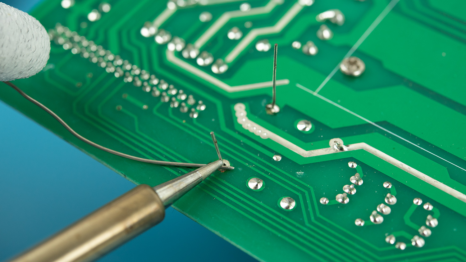
Pre-Tinning the tip before soldering helps to jump start the heat transfer process as the flux cleans the tip and gets the solder flowing before you even touch the joint.
While Tinning before returning the iron to its holder will create a protective coating on the tip. The fresh Solder or Tinner on the tip forms a gas tight seal so oxidation caused by sitting in the open air is dramatically reduced.
For protection, Tip Tinner is the better option because it does not contain any flux acids that will eat away your iron tip.
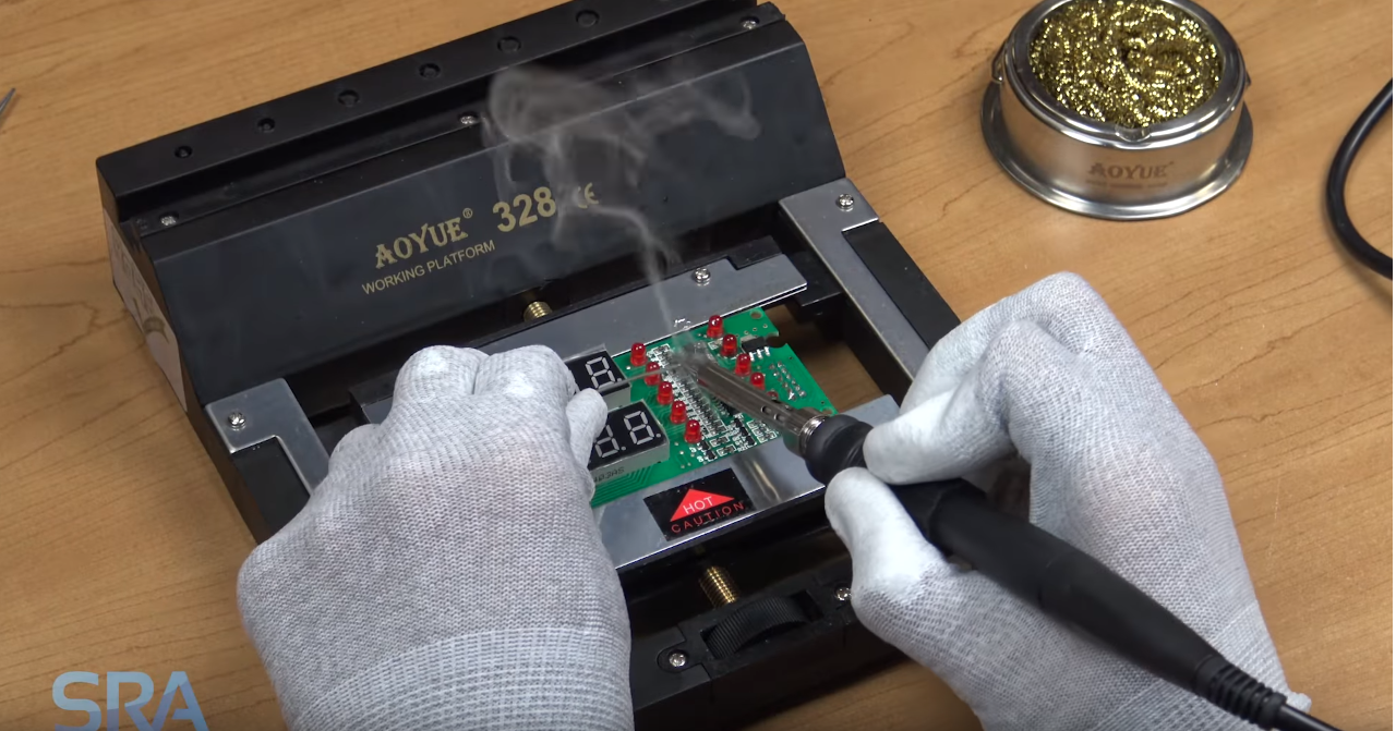
Any solder residue that is left on the iron after coming off a joint should always be cleaned off. If the iron is smoking in the holder that means there is a concentration of flux still on it that needs to be cleaned off. Again, the acidity will eat away at the plating of the tip reducing its life.
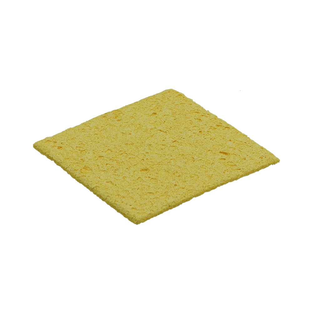
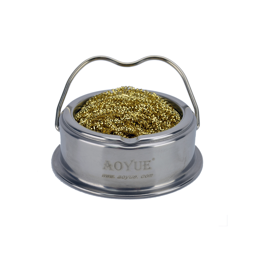
When using your iron for the first time, you will want to perform a renewing cycle of tinning and cleaning until the tip has a nice coating of fresh solder built up and accepts solder easily. Add solder or Tinner all around the tip and clean with your coils/sponge. Repeat until the tip is shiny in appearance and able to melt solder quick and easy. Finish by adding solder or Tinner and returning to its holder.
Oxidation can form over night as well, so still do this at the start of each day before your soldering session for best results.
To get an in-depth explanation on different cleaning and tinning methods checkout our article